Building a simple sensor with the Arduino MKR 1500 NB
This is a very simple example that uses the Arduino MKR 1500 NB to interface with a sensor and to communicate with Span. The cuircuit is very simple - just a microswitch and a potentiometer.
If you want to skip ahead and look at the source code for the sample it is available on GitHub
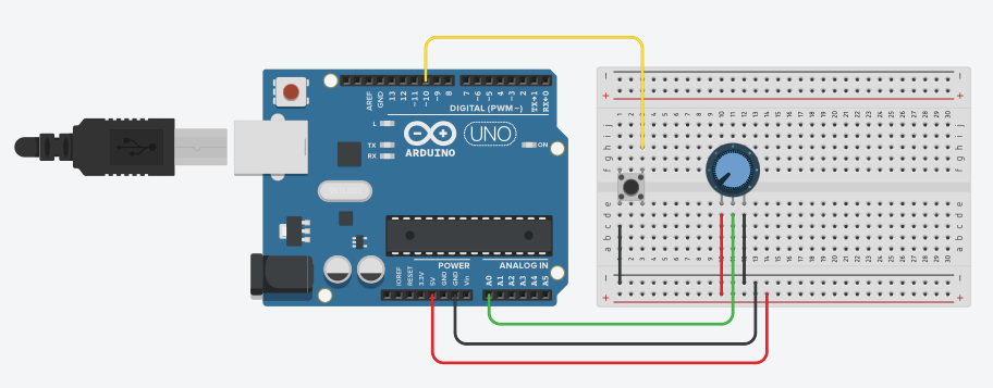
When the switch is pressed the potentiometer reading is sent to Span. The microswitch is wired to GND (the black wire) on one pin and to the digital input on the other pin (the yellow wire). My switch is normally open (they usually are) and when pressed the circuit is closed. I configure the pin to be INPUT_PULLUP so that it will read `HIGH´ unless it is pressed. The potentiometer has the outside wires hooked up to 3.3V (red wire) and GND (black wire). The middle wire is hooked up to the A0 pin on the Arduin.
Note that the illustration shows an Arduino Uno R3 and that the red wire uses the 5V pin, not the 3.3V pin.
About the Arduino MKR 1500 NB
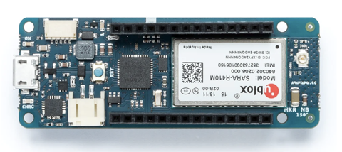
The Arduino MKR 1500 NB is a neat little board. It’s about the same size as a Feather and has everything you need to experiment with NB-IoT. The MCU is upgraded to a SAMD21 Cortex M0 with 32KB memory (it might not sound like a lot but if you are used to the Uno’s 2KB it’s spacious). The board uses 3.3V logic so if you want to use sensors that operate on 5V you should take some care.
When you’re buying the board make sure you get an antenna as well. Mine came without an antenna but I had an Ethertronics antenna lying around. Make sure the antenna is for LTE/Cellular and has an u.FL connector and you should be good to go. If you buy the board from the Arduino store the antenna is bundled with the board.
Register device
Register the device in Span with the IMEI printed on top of the module. This ensures the device will be able to connect when we power it up.
Setup code
In the seutup() function you start by calling begin(NULL, "mda.lab5e") (if you have a Telenor SIM, use lab5e.com4.net if you have COM4 SIM), the call attachGPRS() on the GPRS instance.
Finally, to prepare the UDP sending call begin([local port]) on the UDP object:
GPRS gprs;
NB nbAccess;
NBUDP Udp;
unsigned int localPort = 4200;

void setup()
{
  // Open serial communications and wait for port to open:
  Serial.begin(9600);

  Serial.println("Connecting....");
  boolean connected = false;
  while (!connected) {
    if ((nbAccess.begin(NULL, "mda.lab5e") == NB_READY) &&
        (gprs.attachGPRS() == GPRS_READY)) {
      connected = true;
    } else {
      Serial.println("Not connected, retrying...");
      delay(1000);
    }
  }

  Udp.begin(localPort);
}
Let’s skip the sensors at first and just send a single packet to ensure everything works as expected. Use the following loop code to send a packet:
IPAddress spanAddress(172, 16, 15, 14);
unsigned int spanPort = 1234;

#define PACKET_SIZE 128
byte packetBuffer[PACKET_SIZE];
bool sent = false;

void loop()
{
  if (sent) {
    delay(1000);
    return;
  }
  Serial.println("Sending packet");
  memset(packetBuffer, 0, PACKET_SIZE);
  sprintf((char*)packetBuffer, "Hello world");

  Udp.beginPacket(spanAddress, spanPort);
  Udp.write(packetBuffer, strlen((const char*)packetBuffer));
  Udp.endPacket();
}
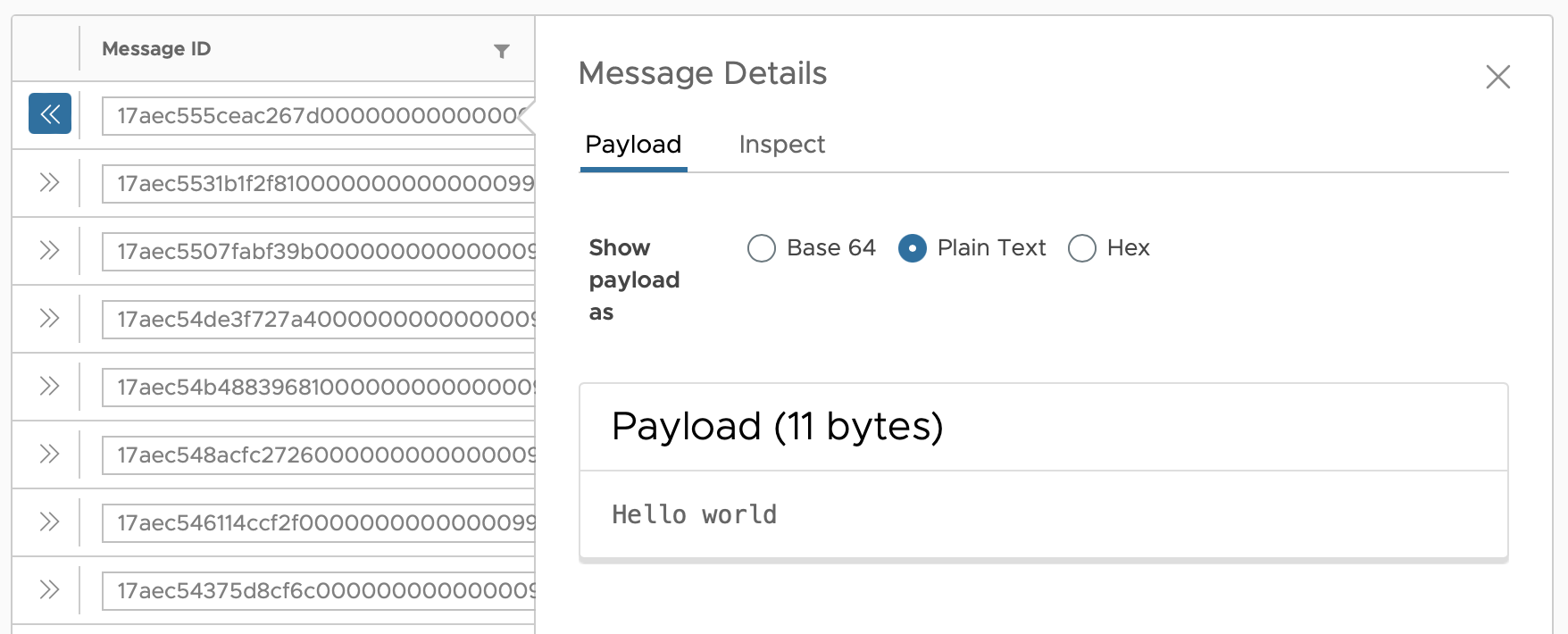
If you run it an watch the Serial Monitor you’ll see Connecting... then Sending packet. If you check out the Inbox in the [Span dashboard] for your device you’ll see the packet as it was sent:
Adding sensors and button
Wire up the circuit above with a microswitch and a potentiometer. If you have a different sensor you want to try out you probably want to use that.
Add the line pinMode(10, INPUT_PULLUP); in the setup code to initialise the pin we’ll read the microswitch from, then replace the loop code with the following:
IPAddress spanAddress(172, 16, 15, 14);
unsigned int spanPort = 1234;

#define PACKET_SIZE 128
byte packetBuffer[PACKET_SIZE];

int potmeterValue = 0;
int lastButtonState = HIGH;
int buttonState = HIGH;

void loop() {
  buttonState = digitalRead(10);
  // put your main code here, to run repeatedly:
  if (buttonState == LOW && lastButtonState != buttonState) {
    potmeterValue = analogRead(A0);
    Serial.print("Sending packet with value ");
    Serial.println(potmeterValue);

    memset(packetBuffer, 0, PACKET_SIZE);
    sprintf((char*)packetBuffer, "Value is %d", potmeterValue);

    Udp.beginPacket(spanAddress, spanPort);
    Udp.write(packetBuffer, strlen((const char*)packetBuffer));
    Udp.endPacket();
  }
  lastButtonState = buttonState;
  delay(100);
}
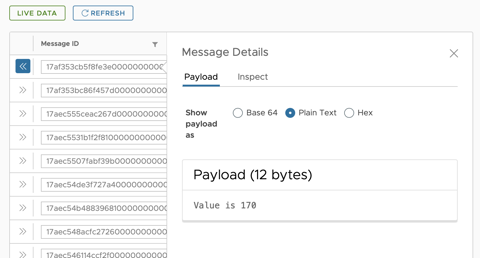
Build it and upload the new firmware to the Arduino. When you press the button the potentiometer reading should be sent to Span and appear in the inbox:
The complete source code for the sample can be found on GitHub.