Sooner or later you’ll come across the terms data rate (DR), spreading factor (SF) and bandwidth (BW). These three terms are related but the link between these aren’t all that obvious.
LoRa uses what is known as a “chirp” protocol, something which was developed for sonar and radar applications during the 2nd world war so it is by no means a new technique.
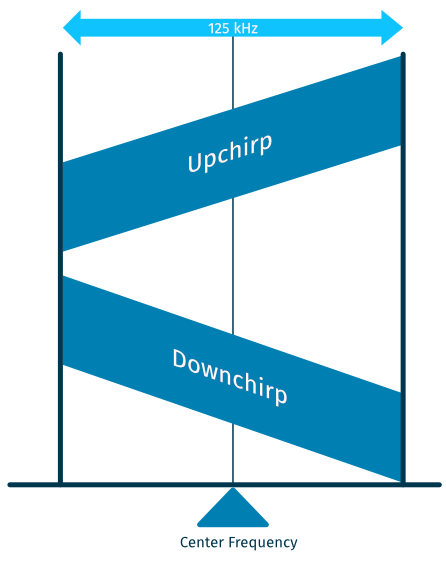
The chirp protocol uses fixed amplitude frequency modulation. It can utilise the entire allocated spectrum to transmit signals by producing a signal that sweeps across the channel. There are two kinds of chirps – the “up-chirp” that moves upward in frequency and (not surprisingly) a “down-chirp” that moves down in frequency, ie when there’s a chirp it will move across the allocated frequency in either direction.
Bandwidth
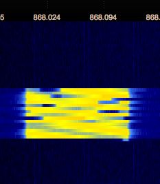
LoRa uses three bandwidths: 125kHz, 250kHz and 500kHz. The chirp uses the entire bandwidth. If you look at a LoRa packet in an SDR application like Gqrx you’ll see a clearly defined square with chirps.
Spreading factor
The spreading factors are - in short - the duration of the chirp. LoRa operates with spread factors from 7 to 12. SF7 is the shortest time on air, SF12 will be the longest. Each step up in spreading factor doubles the time on air to transmit the same amount of data.
With the same bandwidth longer time on air obviously results in less data transmitted per unit of time.
Data Rate
LoRaWAN uses a different configuration of frequencies, spreading factors and bandwidths depending on where you are located in the world. For the EU868, EU433, CN780 and AS923 bands the data rates are as follows:
| Data Rate | Configuration | bits/s | Max payload |
|---|---|---|---|
| DR0 | SF12/125kHz | 250 | 59 |
| DR1 | SF11/125kHz | 440 | 59 |
| DR2 | SF10/125kHz | 980 | 59 |
| DR3 | SF9/125kHz | 1 760 | 123 |
| DR4 | SF8/125kHz | 3 125 | 230 |
| DR5 | SF7/125kHz | 5 470 | 230 |
| DR6 | SF7/250kHz | 11 000 | 230 |
| DR7 | FSK: 50kpbs | 50 000 | 230 |
In the US902-928 an AU915-928 bands the data rates are as follows:
| Data Rate | Configuration | bits/s | Max payload |
|---|---|---|---|
| DR0 | SF10/125kHz | 980 | 19 |
| DR1 | SF9/125kHz | 1 760 | 61 |
| DR2 | SF8/125kHz | 3 125 | 133 |
| DR3 | SF7/125kHz | 5 470 | 250 |
| DR4 | SF8/500kHz | 12 500 | 250 |
| DR8 | SF12/500kHz | 980 | 41 |
| DR9 | SF11/500kHz | 1 760 | 117 |
| DR10 | SF10/500kHz | 3 900 | 230 |
| DR11 | SF9/500kHz | 7 000 | 230 |
| DR12 | SF8/500kHz | 12 500 | 230 |
| DR13 | SF7/500kHz | 21 900 | 230 |
| Data Rate | Configuration | bits/s | Max payload |
|---|---|---|---|
| DR0 | SF12/125kHz | 250 | 59 |
| DR1 | SF11/125kHz | 440 | 59 |
| DR2 | SF10/125kHz | 980 | 59 |
| DR3 | SF9/125kHz | 1 760 | 123 |
| DR4 | SF8/125kHz | 3 125 | 230 |
| DR5 | SF7/125kHz | 5 470 | 230 |
Max payload size matters!
Even though you usually can ignore the selected Data Rate the max payload size means you should limit your payload to the maximum. If your payload exceeds the maximum length you should split it up into multiple pieces.