
Not very long ago someone asked us to come up with something for the ribbon cutting ceremony for the opening of the IoT Protolab here in Trondheim with “IoT” being the operative word. They already had some suggestions that included a samurai sword and a robot but that doesn’t mix well with a room full of people. Strange that.
The IoT Protolab is a joint venture between Wireless Trondheim, Telenor and NTNU.
There wasn’t much time so we had to get something working in a reasonably short time span without being too complex, preferrably something that was internet-of-thing-y, that fitted the setting (a lab for prototypes, electronics and LPWAN work) and is easy to get there and then. We’ve got a few NB-IoT breakouts, Arduinos and Raspberry Pis available so it should be possible to do something with those. Another alternative was to use the EE-04 but we decided against using both LoRaWAN and NB-IoT on the same module, mostly because Arduino is perfect for these kinds of one-offs. They’re cheaper as well. We’ve been working on an Arduino library for the breakout and the beginnings of a backend for the NB-IoT data so why not use those while we’re at it. It’s not like they’ve been tested and we all need some excitement in our lives.
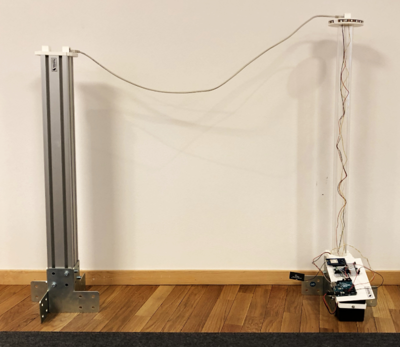
The initial sketch looks like this: Two sticks with lights on top, some wire to cut and… something… happening elsewhere. After a few seconds of contemplation the “something” should be something showing up on a screen, preferably the logo for the new lab.
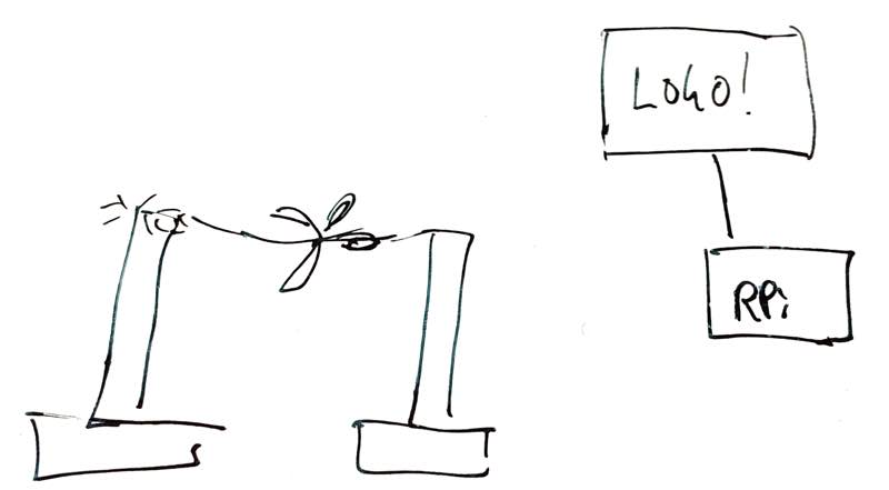
Since both Telenor and NTNU will be sponsoring the new lab the grand opening would be done by both Sigve Brekke, the Telenor CEO, and Gunnar Bovim, the rector of NTNU so we had to have not one but two wires, two posts and two modules. A single center post
From experience blinking lights are always crowd pleasers and if they blink in several different colours it looks even better. We had a few meters of NeoPixel strips lying in the lab so those were decided to use for the top of the posts. As mentioned, the Arduino is brilliant when it comes to these kinds of projects so it was a Small Matter of Code to get a NeoPixel strip (aka WS2812B or SK6812 LEDs) up and running.
Sourcing the hardware
Most of the electronics would be simple: Some arduinos, wires, a few centimetres of a NeoPixel strip. The posts could either be wood, metal or whatever material we could get our hands on. If everything failed we could build it from foam core board. After looking through the office we got lucky and found a piece of acrylic tube that had been lying around for a few years. We chopped it into two pieces and with a base it would make a decent height for the support posts.
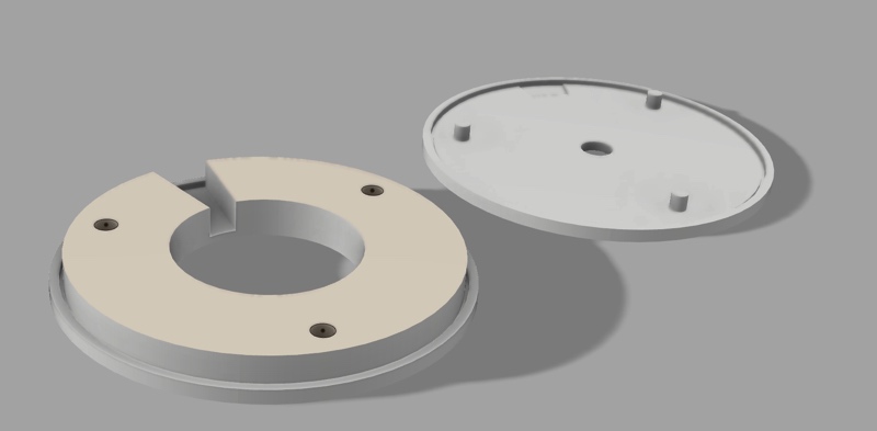
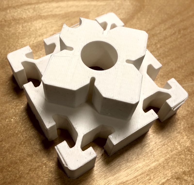
After some short quality time in the Fusion 360 a top to hold the pixel strip was designed. This is the final version with guiding pins for the top, recesses for the wires going to and from the pixel strip and a hole for the wire to be cut in the top:
After rummaging through our secret basement lab (yes, we have one) a few lengths of 8080 aluminium extrusions together with some angle brackets would make decent bases for the posts. With four angle brackets on the bottom they made for a reasonable sturdy bottom while giving off lots of prototype vibes.
For the center post we used one of the still-not-assembled posts since it had just about the right length. It would be a bit short but with one post on each side it wouldn’t look too much out of place.
In addition the whole point of the exercise was to be wireless so we couldn’t use a power cord for the arduinos so we probably had to use some sort of battery. We had a box of D-cells on a shelf and with 15-18 000 mAh for each battery it should work just fine.
Making the control box
Wiring up the Arduino and writing a sketch that flashed lights, checked the state of a wire connected to an internal pullup and sent an NB-IoT packet took just a few hours. This is the setup code:
TelenorNBIoT nbiot = TelenorNBIoT(RX_PIN, TX_PIN);
Adafruit_NeoPixel strip = Adafruit_NeoPixel(
        PIXEL_COUNT, PIXEL_PIN, NEO_GRB + NEO_KHZ800);

void allOff() {
  strip.begin();
  for (uint16_t i = 0; i < strip.numPixels(); i++) {
    strip.setPixelColor(i, 0);
  }
  strip.show();
}

void allRed() {
  strip.begin();
  for (uint16_t i = 0; i < strip.numPixels(); i++) {
    strip.setPixelColor(i, strip.Color(255,0,0));
  }
  strip.show();
}

void showError(uint8_t blinks) {
  for (;;) {
    for (uint8_t i = 0; i < blinks; i++) {
      allRed();
      delay(500);
      allOff();
      delay(500);
    }
    delay(1000);
   }
}

void setup() {
  pinMode(WIRE_PIN, INPUT_PULLUP);
  if (digitalRead(WIRE_PIN) == HIGH) {
    showError(3);
  }
  nbiot.begin();
  if (!nbiot.connect()) {
    showError(1);
  }
}
The showError code might be a bit harsh since it will essentially stop the entire processing if an error occurs but it is nice to know if something is broken.
The loop itself is also quite simple, check state of the wire and either show one pixel strip animation (ie pulsating green lights) while waiting for the wire to be cut or show another pixel strip animation (rotating blue lights) once the wire has been cut. When the wire is cut it will periodically send new packets in case the first one is lost en route to the backend.
The NB-IoT library for Arduino is still way too rough on the edges but we’ll release this quite soon. Stay tuned!
The circuit is embarrassingly simple: Three wires for the pixel strip, two wires for the wire to be cut and four wires to the NB-IoT breakout board.
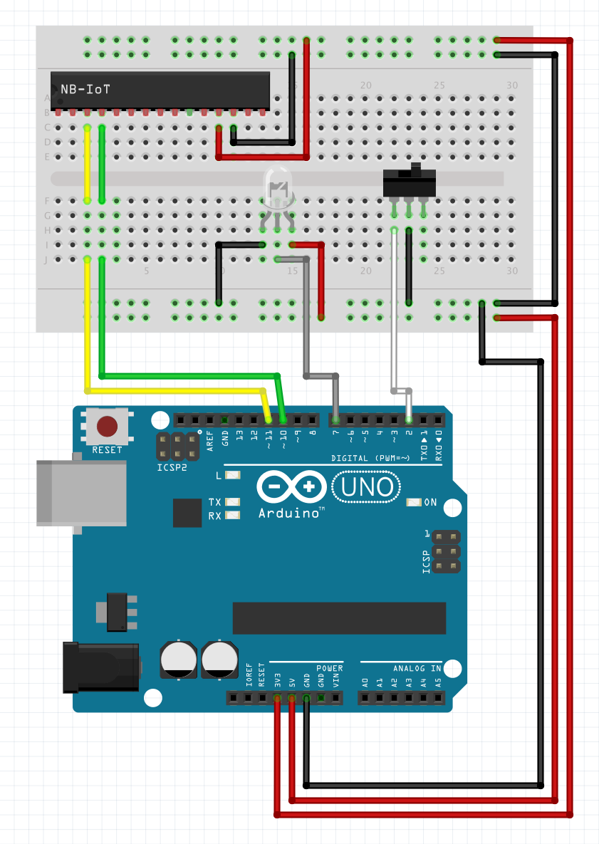
(The single LED represents the strip which requires 5V, GND and a data pin and the switch represents the wire)
The other hardware bits
Rather than hiding the mess of wires we decided to show it off in all its… glory… After all it is the opening of the PROTOlab. Now for power. A stock arduino can be made to use very little power but rather than trying to squeeze the maximum battery life out of the contraption we decided to rely on D cell batteries. They’re nice when space or portability isn’t an issue. Plus we had a box of those lying around. We sourced a box to hold the batteries but as always it didn’t fit just right. As always: The 3D printer took care of that issue: Hans Jørgen designed and printed the required extension to the box and as a nice extra feature we didn’t have to make holes in the battery box so we can reuse it later for other projects. The same bracket got a few holes so that it would attach to the bottom of the angle brackets.
Joining the bases with the acrylic tubing was also simple: More quality time in Fusion 360 with a few hours on the 3D printer gave use adapters for the acrylic tubes in the 8080 extrusions.
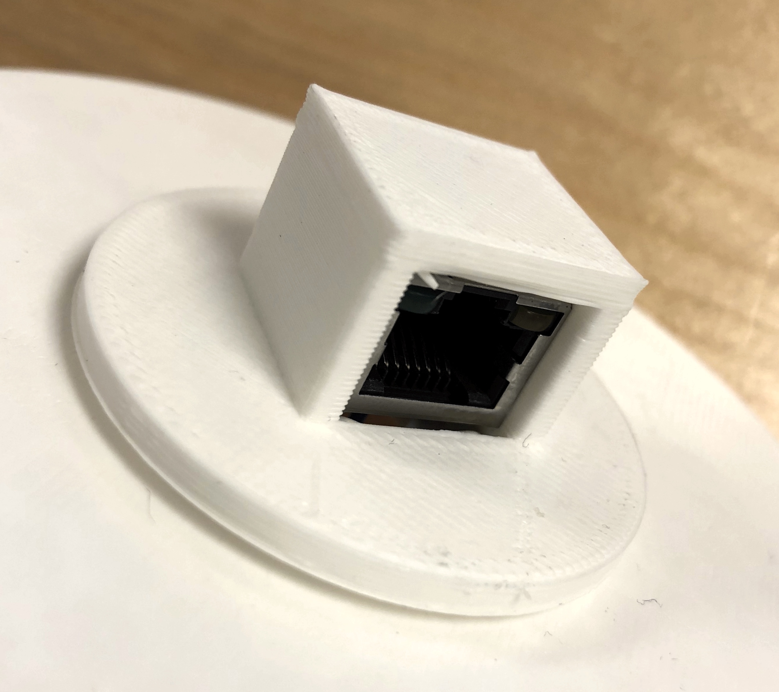
Now for the wires – we had three options: Make a thin wire going through a regular ribbon would probably look best but that would mean going out to some shop and to be perfectly honest we didn’t have a clue where to get a suitable ribbon. Our next alternative is to use a regular wire. That could work but it would have been nice to do a real test of the ribbon cutting before the grand opening and that would mean replacing the wire which would again mean more soldering and more things that could go wrong. We had initially thought about using network cables (they’re cheap and plentiful) but soldering jumper wires on to strands of network cables are a recipe for disaster since they easily break. Fortunately Thomas have been working on motor controllers to our PnP machine and had a few RJ45 connectors. RJ45 connectors are nice when you want to replace wires. The non-connected part were shorted across all of the pins and all we had to do on the Arduino side was to connect two random wires to the other plug. Once more Fusion 360 and the 3D printer came to the rescue and the casing were glued to the top of the post.
Software on the Raspberry Pi
The Raspberry Pi code is releatively trivial: Print two grayed-out logos when starting up, listen for data from the two devices and once they’ve sent data highlight the appropriate logo. The arduinos were programmed to send - not surprisingly - “Telenor” and “NTNU”. It’s all written in Go since cross-compiling to the RPi is as simple as GOOS=linux GOARCH=arm go build and the Go standard libraries includes support for PNG encoded images.
This code snippet reads the file from disk:
func loadFile(imagefile string) (image.Image, error) {
    fileinfo, err := os.Lstat(imagefile)
    if err != nil {
        return nil, errors.New("unable to stat image file")
    }
    buf := make([]byte, fileinfo.Size())

    file, err := os.Open(imagefile)
    if err != nil {
        return nil, errors.New("unable to open image file")
    }
    defer file.Close()
    n, err := file.Read(buf)
    if err != nil {
        return nil, errors.New("unable to read image file")
    }

    img, err := png.Decode(bytes.NewReader(buf[0:n]))
    if err != nil {
        return nil, errors.New("unable to decode image file")
    }
    return img, nil
}
…and displaying it on the framebuffer is equally simple (rgbaImage is an image.Image instance):
if runtime.GOOS != "linux" {
    return
}
const fbDevice = "/dev/fb0"
if fbbuf == nil {
    fbbuf = make([]byte, params.screenWidth*params.screenHeight*4)
}
pos := 0
for y := 0; y < params.screenHeight; y++ {
    for x := 0; x < params.screenWidth; x++ {
        r, g, b, a := rgbaImage.At(x, y).RGBA()
        fbbuf[pos] = byte(b & 0xFF)
        pos++
        fbbuf[pos] = byte(g & 0xFF)
        pos++
        fbbuf[pos] = byte(r & 0xFF)
        pos++
        fbbuf[pos] = byte(a & 0xFF)
        pos++
    }
}
if err := ioutil.WriteFile(fbDevice, fbbuf[0:pos], 0600); err != nil {
    fmt.Println("Error writing to frame buffer: ", err)
}
Since the RPi uses HDMI for its output the image can either be put on a big screen or a projector, whatever is available. It is also a bog standard HD signal at 1080i so it won’t be any surprises there.
Five different images are used, two for the inactive logos, two for the highlighted logos and one for the IoT Protolab logo itself. Whenever one of the packets are received the appropriate logo is drawn to the framebuffer. Since the framebuffer update is really quick we just redraw the entire screen when necessary.
The source is available at GitHub if you want to have a look. It’s not very pretty but it does its job.
Assembling everything… and testing
The firmware and RPi software was relatively straight forward, ditto with the breadboard. Wiring everything up in a semi-reliable fashion was a bit more complicated. Since we didn’t know the exact dimensions it was a fair bit of guesswork involved and we didn’t glue the parts together in case we changed our minds (which we did several times during the build). After some soldering, re-soldering, re-re-soldering, de-soldering and re-re-re-soldering it worked. Sort of. The Arduino library is a bit rough around the edges as mentioned earlier and the NB-IoT backend service has its quirks so we had about a 50/50 success rate during the tests. During the build we had to manually solder a few more NB-IoT breakouts and getting a new board running can be exciting in and of itself. With just a few minutes left we had a working pair of posts, loaded up very carefully into the back of Thomas’ car and did a first on-site test. There were a few issues but after getting everything up and running we felt slightly more confident.
With some more time we’d probably try out the PCB mill at Protolab to make the whole thing just a little more presentable. If they decide to do another grand opening we are ready!
On The Big Day we were more than a little apprehensive to put it mildly. There were lots of things that could go wrong: Bad wires, packets dropped, short circuits and… Well - you get the idea. We could have implemented a plan B but we didn’t get around to that part. Fortunately it worked out just fine - in fact so well that the majority suspected we cheated and used PowerPoint. That would have been less nerve-wrecking but where’s the fun in that?
If you want to see the opening you can have a look at videos from the opening (both on Facebook and in Norwegian) here and here.